The Role Of A 4x1 Mux Logic Diagram In Creating Complex Computational Hardware Systems And Data Selectors - (a) the 3mr system; (b) 3-input majority voter based on the multiplexer ...
If you are searching about [CUSTOM IC ONE CHIP] 4X1 MUX - Logic OR Switch (15) you've came to the right web. We have 35 Images about [CUSTOM IC ONE CHIP] 4X1 MUX - Logic OR Switch (15) like 16x1 Mux Using 8x1 Mux and 2x1 Mux | PDF, Interlinked computers creating server network, providing required and also 1. Draw the circuit diagram and truth table for a 2x1 multiplexer. 2. Here it is:
[CUSTOM IC ONE CHIP] 4X1 MUX - Logic OR Switch (15)
![[CUSTOM IC ONE CHIP] 4X1 MUX - Logic OR Switch (15)](https://img1.daumcdn.net/thumb/R800x0/?scode=mtistory2&fname=https:%2F%2Fblog.kakaocdn.net%2Fdn%2FMGVxZ%2FbtsNAOL1n67%2FgfNK7tXGcg3myP2nL0y1r0%2Fimg.png) whehdud2.tistory.com
whehdud2.tistory.com
[CUSTOM IC ONE CHIP] 4X1 MUX - Logic OR Switch (15)
Karnaugh Map - Need Help Understanding Multiplexer (MUX) Inputs And K
 electronics.stackexchange.com
karnaugh map - Need help understanding multiplexer (MUX) inputs and K ...
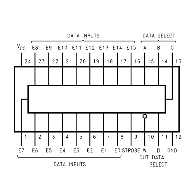
74150 Data Selectors/Multiplexers | Makers Electronics
 makerselectronics.com
74150 Data Selectors/Multiplexers | Makers Electronics
Applications Of MUX - GeeksforGeeks
 www.geeksforgeeks.org
Applications of MUX - GeeksforGeeks
Interlinked Computers Creating Server Network, Providing Required
 www.alamy.com
Interlinked computers creating server network, providing required ...
Multiplexer And Demultiplexer Circuit Diagram Truth Table
 www.circuitdiagram.co
Multiplexer And Demultiplexer Circuit Diagram Truth Table
CircuitVerse - 4X1 MUX USING FULL ADDER
 circuitverse.org
CircuitVerse - 4X1 MUX USING FULL ADDER
What Is A Mux Gate At Robert Trisha Blog
 storage.googleapis.com
What Is A Mux Gate at Robert Trisha blog
(a) The 3MR System; (b) 3-input Majority Voter Based On The Multiplexer
 www.researchgate.net
(a) The 3MR system; (b) 3-input majority voter based on the multiplexer ...
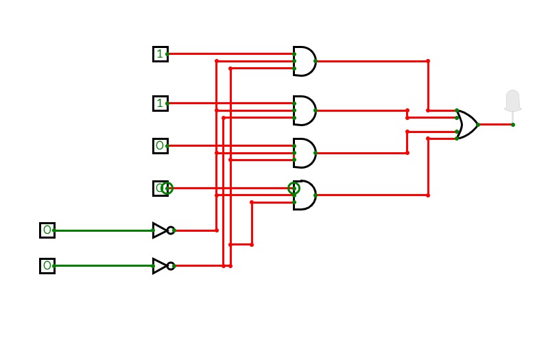
CircuitVerse - 4x1 MUX Using Logic Gates
 circuitverse.org
CircuitVerse - 4x1 MUX using logic gates
Digital Logic - For The 4x1 MUX Shown Below The Boolean Expression F(x
 electronics.stackexchange.com
digital logic - For the 4x1 MUX shown below the Boolean Expression F(x ...
4 To 1 Multiplexer Circuit Diagram And Truth Table » Diagram Board
 www.diagramboard.com
4 To 1 Multiplexer Circuit Diagram And Truth Table » Diagram Board
Mux Lamas
 fity.club
Mux Lamas
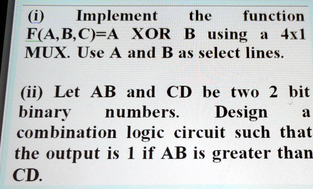
SOLVED: Implement The Function Using 4x1 MUX Implement The Function F(A
 www.numerade.com
SOLVED: Implement the function using 4x1 MUX Implement the function F(A ...
Alu Circuit Diagram Using Multiplexers
 www.circuitdiagram.co
Alu Circuit Diagram Using Multiplexers
Multiplexer Truth Table And Circuit Diagram » Wiring Diagram
 www.wiringview.com
Multiplexer Truth Table And Circuit Diagram » Wiring Diagram
What Is A Mux Circuit At Heidi Lucille Blog
 storage.googleapis.com
What Is A Mux Circuit at Heidi Lucille blog
Data Flow Modeling In Verilog - Circuit Fever
 circuitfever.com
Data Flow Modeling In Verilog - Circuit Fever
Design Gates Using Mux At Amy Beasley Blog
 storage.googleapis.com
Design Gates Using Mux at Amy Beasley blog
MUX Based On (a) Logic Gates And (b) Transmission Gates | Download
MUX based on (a) Logic Gates and (b) Transmission Gates | Download ...
Draw The Logic Diagram Of A Four-bit Register With Four D Flip-flops
 www.numerade.com
Draw the logic diagram of a four-bit register with four D flip-flops ...
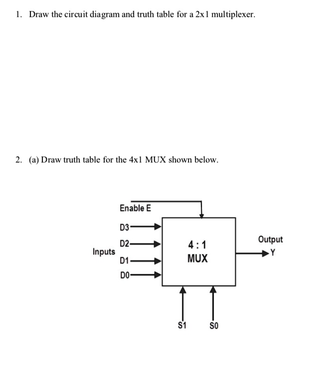
1. Draw The Circuit Diagram And Truth Table For A 2x1 Multiplexer. 2
 www.numerade.com
1. Draw the circuit diagram and truth table for a 2x1 multiplexer. 2 ...
Multiplexer Circuit Diagram And Truth Table
 www.circuitdiagram.co
Multiplexer Circuit Diagram And Truth Table
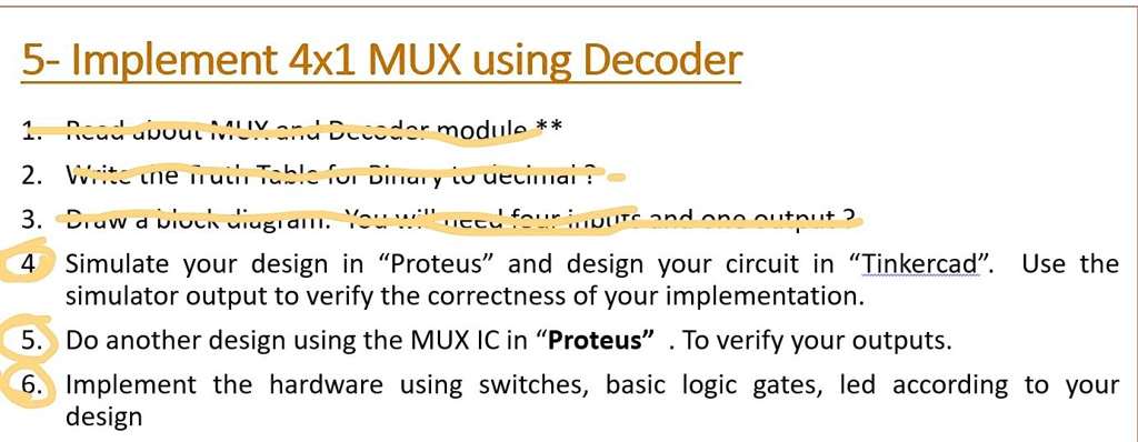
SOLVED: 5- Implement 4x1 MUX Using Decoder Output Module ** 4 Simulate
 www.numerade.com
SOLVED: 5- Implement 4x1 MUX using Decoder Output Module ** 4 Simulate ...
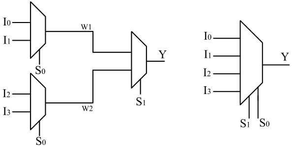
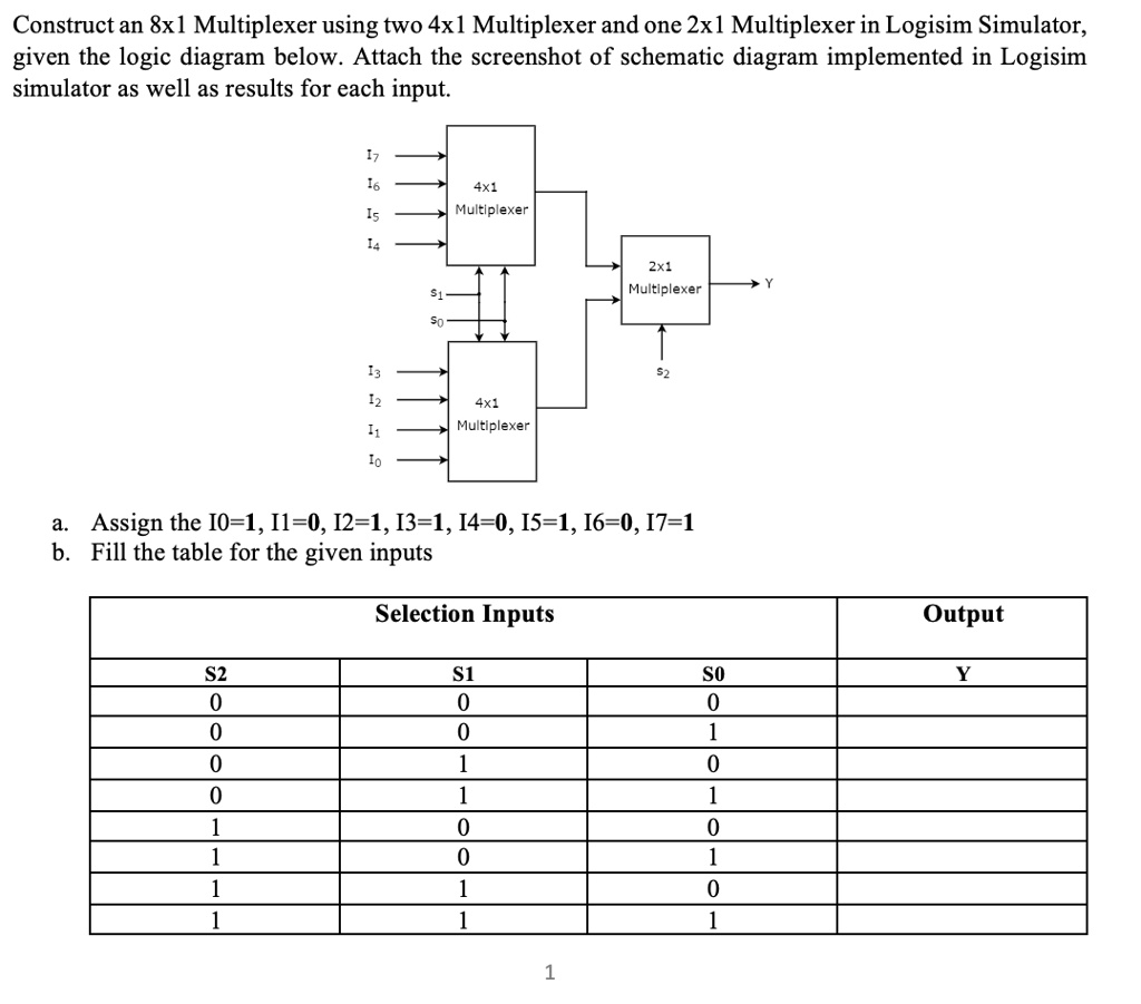
SOLVED: Construct An 8x1 Multiplexer Using Two 4x1 Multiplexers And One
 www.numerade.com
SOLVED: Construct an 8x1 Multiplexer using two 4x1 Multiplexers and one ...
Determine The Output F Of The 4x1 MUX Shown In The Diagram. The Options A..
 askfilo.com
Determine the output F of the 4x1 MUX shown in the diagram. The options a..
CircuitVerse - FULL SUBTRACTOR USING 4x1 MUX
 circuitverse.org
CircuitVerse - FULL SUBTRACTOR USING 4x1 MUX
2 1 Mux Circuit Diagram
 www.circuitdiagram.co
2 1 Mux Circuit Diagram
8 To 1 Multiplexer Circuit Diagram
 stewart-switch.com
8 To 1 Multiplexer Circuit Diagram
Digital Logic - Block Diagram Of 16:1 MUX Using Four 4:1 MUX Only
 electronics.stackexchange.com
digital logic - Block diagram of 16:1 MUX using four 4:1 MUX only ...
16x1 Mux Using 8x1 Mux And 2x1 Mux | PDF
 www.scribd.com
16x1 Mux Using 8x1 Mux and 2x1 Mux | PDF
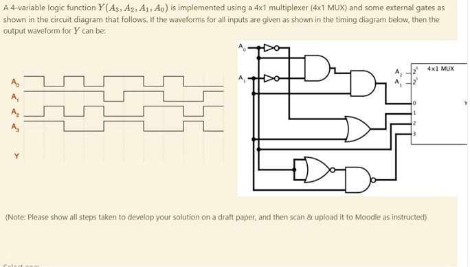
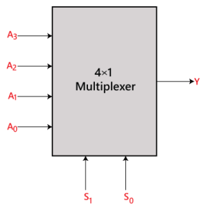
A 4-variable Logic Function Y(A3, A2, A1, A0) Is Implemented Using A
 www.numerade.com
A 4-variable logic function Y(A3, A2, A1, A0) is implemented using a ...
4x1 Multiplexer Truth Table » Diagram Board
 www.diagramboard.com
4x1 Multiplexer Truth Table » Diagram Board
8 To 1 Multiplexer Circuit Diagram
 stewart-switch.com
8 To 1 Multiplexer Circuit Diagram
4 1 Mux Circuit Diagram
 www.circuitdiagram.co
4 1 Mux Circuit Diagram
1. draw the circuit diagram and truth table for a 2x1 multiplexer. 2. Applications of mux. Digital logic